High-voltage System Components

Table of Contents
High-voltage System Overview
Wiring and Connector Concept
High-voltage System Components
Thermal Management
High-voltage Safety Concept
Driving Mode Selection

Network
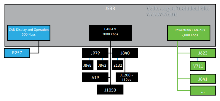
The control units for the high-voltage components are connected to two data-bus systems.
Both are 2,000 kBaud, ensuring high-speed information exchange.

• CAN EV
• Powertrain CAN bus

Actuator 1 for Engine Sound Generator R257 is controlled by the CAN Display and Operation unit.


1666626357186.png

Key
A19 Voltage Converter
J623 Engine/Motor Control Module
J840 Battery Regulation Control Module
J841 Electric Drive Control Module
J842 A/C Compressor Control Module
J848 High-Voltage Heater (PTC) Control Module
J979 Heating and Air Conditioning Control Module
J1050 High-Voltage Battery Charger Control Module
J1208 Battery Module Control Module
R257 Engine Sound Generator Actuator 1
V711 Radiator Blind Adjustment Motor
Z132 Heating Element (PTC) 3


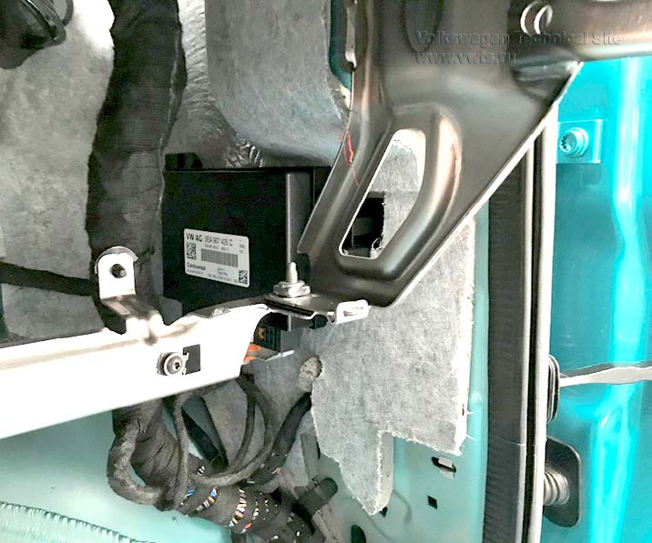
J623 Engine Control Module - Location and Functions

The ECM is located on the right A-pillar in the vehicle interior.

It has the following key functions:
• Implementation of driver assist systems
• Management of the torque requirement
• Management of energy recovery intensity
• Thermal management
• Monitoring the high-voltage components (high-voltage coordination)

The ECM performs the same functions as it does in all other high-voltage vehicles.
The new central processor does not require the hybrid data-bus.
The components are divided up into three different systems (CAN-EV, powertrain CAN-bus and CAN display and operating unit).

 
1666626488465.png


The following components are connected directly to the ECM:
• Accelerator Pedal Module GX2
• Temperature Sensor G18
• Radiator Fan VX57
• Control Motor for Radiator Roller Blind V711 (LIN-Bus)
• Coolant Pump for Low-temperature Circuit V468

When energy recovery is performed, the CAN-Bus sends a signal to the
Onboard Supply Control Module J519 that controls the brake lights.


J623 Engine Control Module - High-Voltage Coordination

The high-voltage coordinator in the J623 manages the activation and deactivation sequence for the high-voltage system, and also prevents a system start if any anomalies occur in high-voltage components.
Its functions are:
• Coordination of all high-voltage sub-systems and networks involved
• Implementation of defined operating states
• Interface between the high-voltage functions and the other vehicle systems

High-voltage sub-systems refer to high-voltage functions that only require individual high-voltage components for implementation. For example:
• The High-Voltage Battery 1 AX2 and the Charging Unit 1 for High-Voltage Battery AX4 are responsible for the charging process
• The High-Voltage Battery 1 AX2, the Air Conditioner Compressor VX81 and the High-Voltage Heater (PTC) ZX17 are responsible for the air conditioning

Engine Sound Generators

The VW ID.4 has two engine sound generators to make the vehicle noticeable to pedestrians. One sound generator is located at the front of the vehicle, and one is
located in the rear. The front sound generator is covered on this page, and the rear sound generator is covered on the next page.

Sound is generated:
• When the vehicle is stationary with a forward or reverse gear selected
• in vehicle operation at speeds up to approximately 20 mph (25 km/h) in both forward and reverse


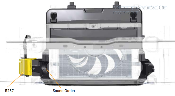
Engine Sound Generator Actuator 1 RX21 - Location and Function

The Actuator 1 for Engine Sound Generator RX21 is located on the front right side of the vehicle behind the bumper.
Sound is generated out the front of the vehicle. It is made up of:
• The Engine Sound Generator Actuator 1 R257
• The Engine Sound Generator Control Module J943

 
1666626871389.png


Engine Sound Generator Module 2 RX22 - Location and Function

The Actuator for Engine Sound Generator Module 2 RX22 is located on the rear right side of the vehicle behind the bumper.
Sound is generated out the rear of the vehicle when a forward or reverse gear is selected.
Sound output is directed towards the road surface.

It is made up of:
• The Engine Sound Generator Actuator 2 R258
• The Engine Sound Generator Control Module 2 J1167

 
1666626999504.png


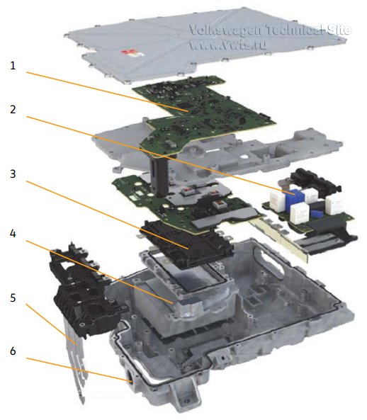
JX1 Electric Drive Power and Control Electronics - Location and Design

The Power and Control Electronics for Electric Drive JX1 are located on the three-phase current drive.

They consist of the following components:
1. J841 Electric Drive Control Module
2. EMC and suppression filter
3. A37 Drive Motor Inverter
4. C25 Intermediate Circuit Capacitor 1
5. V141 Electric Drive Motor
6. Connections for coolant

 
1666627101779.png


The JX1 Electric Drive Power and Control Electronics are cooled using the VX54
Three-Phase Current Drive in the low-temperature cooling circuit.

The JX1 is new and has improved current carrying capacity and continuous
output. It has a watertight connection to the VX54 that can be replaced
separately. The power electronics and e-machine are a single unit. If they are
separated for any service procedures, a tightness test must be performed when
assembling. No components in the JX1 can be replaced.


JX1 Electric Drive Power and Control Electronics - Functions

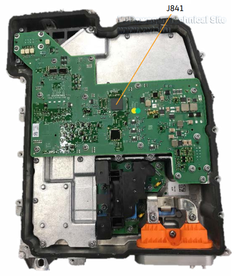
The J841 Electric Drive Control Module is located inside of the JX1 and cannot be replaced separately.

It has the following functions:
• Implementation of the driver’s request
• Monitoring the three-phase current drive temperature
• Rotor position identification

The following components are connected to the control module:
• G712 Drive Motor Temperature Sensor
• G713 Drive Motor Rotor Position Sensor 1

 
1666627249433.png


It regulates and monitors the three-phase current drive and controls the A37 DC/AC
Converter for Drive Motor for the three-phase alternating voltage.

JX1 Electric Drive Power and Control Electronics - Functions

The J841 Electric Drive Control Module uses G713 Drive Motor Rotor Position Sensor 1 to determine the speed and the position of the rotor in the V141 Electric
Drive Motor. This data is used for exact activation of the electric drive motor.
The G712 Drive Motor Temperature Sensor is used to determine the temperature of the V141.
The component temperatures are determined using internal temperature sensors in the JX1 in the J841.


VX54 Three-Phase Current Drive - Location

The three-phase current drive is located in the rear of the vehicle together with the JX1 Electric Drive Power and Control Electronics.
It is connected to the lowtemperature cooling circuit.

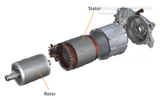
It has the following components:
• V141 Electric Drive Motor (rotor and stator)
• G712 Drive Motor Temperature Sensor
• G713 Drive Motor Rotor Position Sensor 1

 
1666627425595.png


The stator for the V141 is manufactured using the hairpin method. The individual stator elements look like hair pins, which is where the name comes from.
In addition to the advantages for automated high volume production, the stator features better heat dissipation and lower rotor losses when compared to wound coil designs.


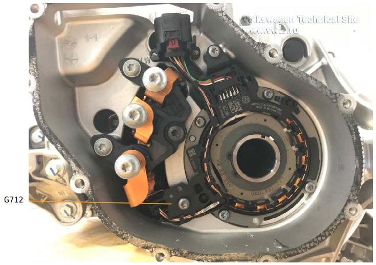
VX54 Three-Phase Current Drive - G712 Drive Motor Temperature Sensor

The G712 Drive Motor Temperature Sensor is located between two stator solenoids to improve signal detection.
It is a Negative Thermal Coefficient (NTC) sensor and reports the temperature to the JX1 Electric Drive Power and Control Electronics.
The signal is needed to prevent overheating of the V141 Electric Drive Motor. The de-rating of VX54 begins at approx. 160°C

 
1666627582016.png


VX54 Three-Phase Current Drive - G713 Drive Motor Rotor Position Sensor 1

G713 Drive Motor Rotor Position Sensor 1 is installed on the VX54 Three-Phase Current Drive and functions as an inductive sender with advanced evaluation.
The sensor wheel is attached to the rotor of the electric drive motor, which drives it.
The G713 determines the position, the direction of rotation and component tolerances.
It has a direct connection to the JX1 Electric Drive Power and Control Electronics.

 
1666630226775.png


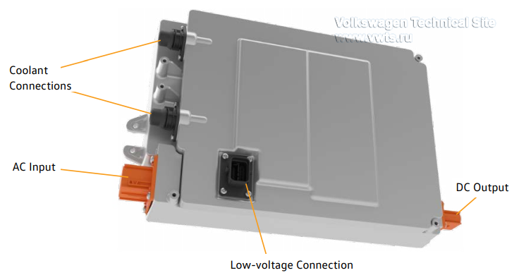
AX4 High-Voltage Battery Charger 1

The AX4 is located in the rear of the vehicle. It converts any Alternating Current (AC) into Direct Current (DC) for the high-voltage battery.
The charging unit is regulated by the J1050 High-Voltage Battery Charger Control Module, which monitors and regulates the charging process.
The DC charging process is also monitored and regulated by the J1050. A maximum DC charging rate of 125 kW is possible for the 82 kWh battery.

These components have a direct connection to AX4:
• F496 High-Voltage Charge Door Lock 1 Adjuster
• L263 Charging Socket 1 LED Module
• F498 High-Voltage Charging Connector Lock 1 Adjuster
• UX4 High-Voltage Battery Charging Socket 1 with G853 Charging Socket Temperature Sensor 1
• G1151 Charging Socket 2 Temperature Sensor 1
• G1152 Charging Socket 3 Temperature Sensor 1

 
1666630423808.png


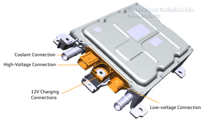
A19 Voltage Converter - Location and Functions

The A19 is located in the front of the vehicle and supplies the 12 V electrical system with energy. It has a maximum power of 16 V.

The A19 uses bidirectional operation to charge and discharge the C25 Intermediate Circuit Capacitor 1 located in the JX1.
This is why it is an additional source of high-voltage to supplement the AX2 High-Voltage Battery 1.
It must also be checked to ensure it is de-energized when the high-voltage system is deactivated. It is cooled by coolant.

The bidirectional operation of the voltage converter is only used for charging/discharging the C25. Recharging the high-voltage battery is not possible.

Connections:
• Terminal 30, 30 A
• Terminal 31
• HV-positive and HV-negative
• CAN-EV

 
1666630569719.png


ZX17 High-Voltage Heater (PTC) - Location and Functions

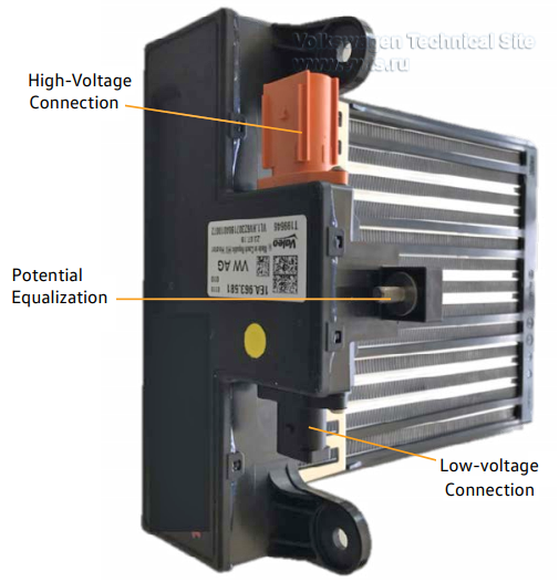
The ZX17 is installed in the air-conditioning box in the VW ID.4.
It heats the interior air and is infinitely variable using Pulse-Width Modulation (PWM).
The High-Voltage Heater has a J848 High-Voltage Heater (PTC) Control Module of its own.
This is controlled and monitored by the J979 Heating and Air Conditioning Control Module by means of LIN-Bus.

 
1666630789830.png


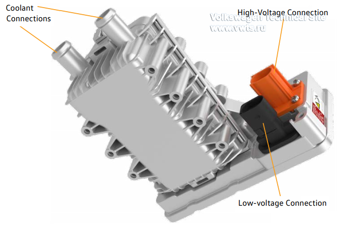
Z132 Heating Element (PTC) 3 - Location and Function

The Z132 is located in the front end of the Volkswagen ID.4.
It heats up the coolant for the high-voltage battery and is infinitely variable using Pulse-Width Modulation (PWM).
Temperature sensors are located in the coolant inlet and outlet.
The Z132 is connected to the J840 Battery Regulation Control Module by LIN-Bus.

 
1666631056453.png


AX2 High-Voltage Battery 1 - Location

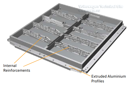
The AX2 is located between the axles under the vehicle.
The battery housing is made of aluminium. Reinforcements have been installed inside the housing to provide the battery modules with the best possible
protection in the event of an accident, both in the longitudinal and the lateral directions.
There are additional lateral reinforcements below the housing.
The housing is surrounded by solid extruded aluminium profiles.

 
1666631227640.png


AX2 High-Voltage Battery 1 - Battery Designs

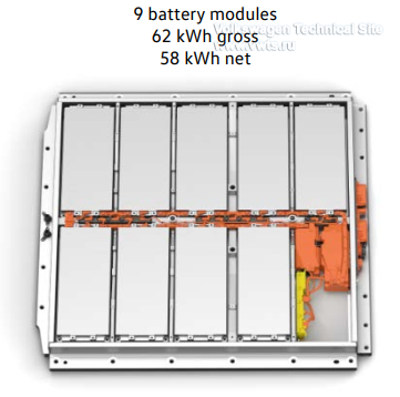
There are two versions of the AX2 used in the VW ID.4 due to size and energy content.
Only the 82 kWh battery will be available at launch.

The maximum AC charge rate for each battery is:
• 7.2 kW for the 62 kWh battery
• 11 kW for the 82 kWh battery

The maximum DC charge rate for each battery is:
• 50 kW for the 62 kWh battery
• 125 kW for the 82 kWh battery

 
1666631334716.png


1666631354509.png


AX2 High-Voltage Battery 1 - Components

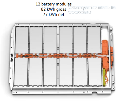
This is the VW ID.4 with an energy content of 82 kWh. The components in the 62 kWh battery are similar.
Many battery components can be replaced for service procedures.

 
1666631505064.png


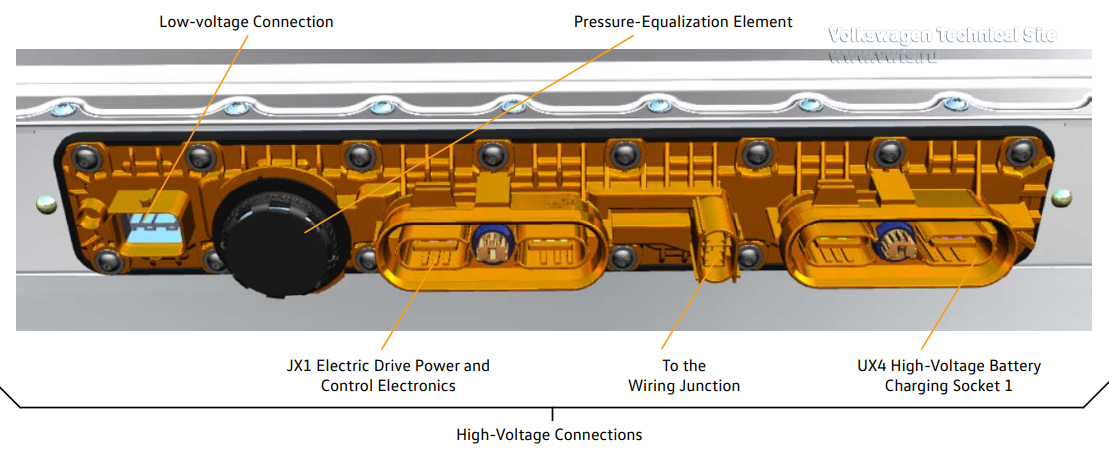
AX2 High-Voltage Battery 1 - Electrical Connections in the AX2

 
1666631677978.png


Assignment of the low-voltage connection T32g:
• Terminal 30
• Terminal 30C
• Terminal 31
• J234 Airbag Control Module
• G898 High-Voltage Battery Coolant Temperature Sensor 1
• G899 High-Voltage Battery Coolant Temperature Sensor 2
• Pilot line
• Z132 Heating Element (PTC) 3
• Powertrain CAN bus
• V590 High-Voltage Battery Coolant Pump
• V683 Mixing Valve for High-Voltage Battery Warming
• V696 Mixing Valve 2 for High-Voltage Battery Warming


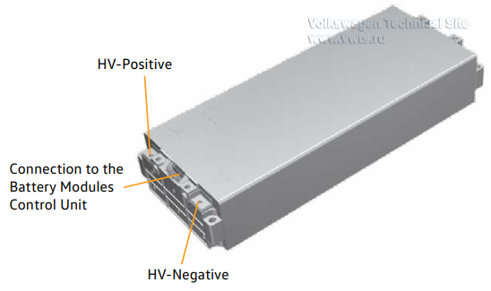
AX2 High-Voltage Battery 1 - Battery Module

The battery modules of the VW ID.4 may have either prismatic cells or pouch cells. Prismatic lithium-ion cells made by LG will be used upon launch.
Other suppliers may be added, depending on the market and date of use. Battery modules with different cell types will not be used in one battery.
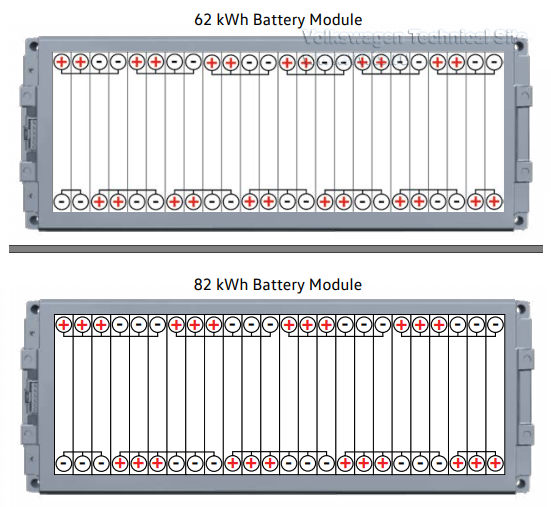
The battery modules are configured as 8 in series and 3 in parallel in the battery with 82 kWh.
For the 62 kWh battery, the modules are arranged as 12 in series and 2 in parallel
Due to the encapsulated aluminum housing, internal module circuit configuration can’t be determined.
The difference is only indicated by the part number.

Technical Data
 
  62 kWh 82 kWh
Cell technology Lithium-ion Lithium-ion
Cell type Prismatic Prismatic
Manufacturer LG LG
Capacity per battery cell 78 Ah 78 Ah
Number of cells 24 24
Circuitry of the module 12 in series, 2 in parallel 8 in series, 3 in parallel
Number of modules in battery 9 12
Capacity of the module 156 Ah 234 Ah
Nominal voltage of the module 44.4 V 29.6 V
Energy content of the module 6.926 kWh 6.926 kWh
Weight per module approx. 66 lbs (30 kg) approx. 66 lbs (30 kg)

 
1666631932681.png


1666632012364.png


AX2 High-Voltage Battery 1 - Switching Units

The components and functions have been divided up between two switching units.
This allows them to fit into the different spaces required by the different high-voltage batteries.

The intermediate circuit capacitor 1 C25 in the JX1 Electric Drive Power and Control Electronics in the VW ID.4 is pre-charged by the A19 Voltage Converter.
This eliminates the need for a pre-charge relay and a pre-charge resistor.

 
1666632218993.png


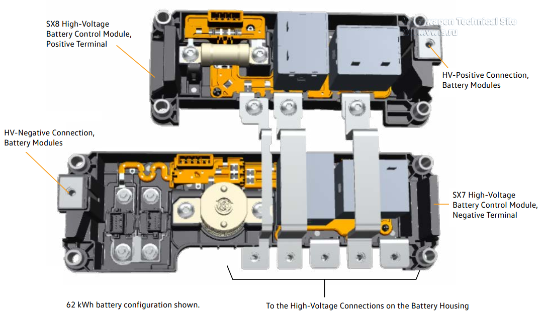
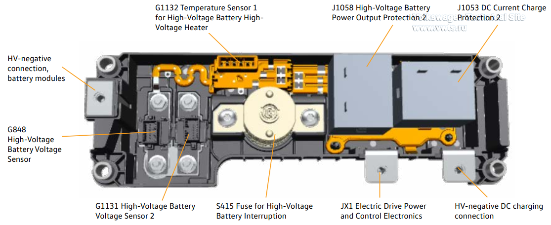
AX2 High-Voltage Battery 1 - Switching Unit for SX7 High-Voltage Battery Control Module, Negative Terminal

The S415 Fuse for High-Voltage Battery Interruption is a pyrotechnic fuse and increases the level of safety in the high-voltage system.
In the event of a fault, it can trip faster than a high-voltage relay. If the fuse has tripped, the entire SX7 unit must be replaced.
It cannot be replaced or reset.
There are voltage taps on the high-voltage connectors.
The J840 Battery Regulation Control Module uses these to monitor the high-voltage connectors.

 
1666632418657.png


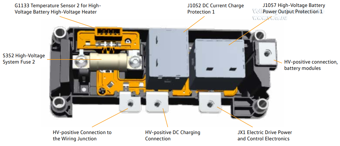
AX2 High-Voltage Battery 1 - Switching Unit for SX8 High-Voltage Battery Control Module, Positive Terminal

The SX8 unit has an internal S352 High-Voltage System Fuse 2. Once tripped, this fuse cannot be replaced or reset, requiring replacement of the entire SX8 unit.
This fuse protects the following high-voltage sub-components

• AX4 High-Voltage Battery Charger 1
• Z132 Heating Element (PTC) 3
• ZX17 High-Voltage Heater (PTC)
• VX81 A/C Compressor
• A19 Voltage Converter

 
1666632688779.png


AX2 High-Voltage Battery 1 - J840 Battery Regulation Control Module

Functions of the J840:
• Communication using the powertrain CAN-bus
• Master control unit for the internal data-bus system
• Monitoring and controlling the switching units in the high-voltage battery
• Monitoring of the pilot line
• Insulation resistance monitoring
• Provision of measured values for the high-voltage battery
• Activation of the S415 Fuse for High-Voltage Battery Interruption in the event of a fault

 
1666632742895.png


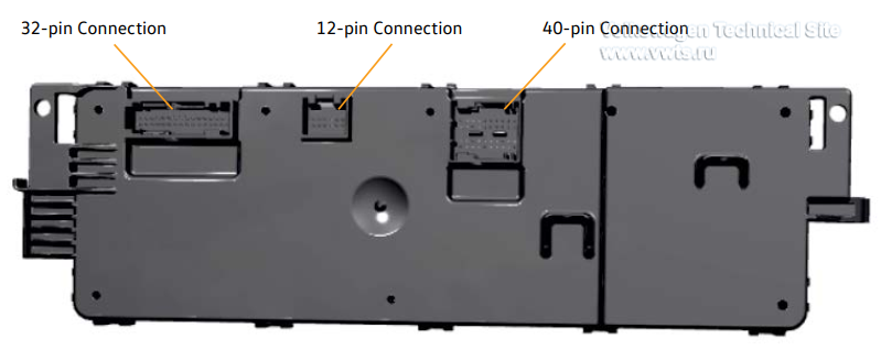
AX2 High-Voltage Battery 1 - J840 Battery Regulation Control Module

Pin assignment on the J840:

• 32-pin connection:
– Connection to the low-voltage connector on the battery housing (see electrical connections for AX2)
– Connection to the J1208–J1210 Battery Modules Control Modules (CAN-bus and LIN-bus)
– Additional Ground connection to the battery housing

• 12-pin connection:
– Voltage signals before and after the high-voltage connectors in the switching units for high-voltage battery

• 40-pin connection:
– S415 Fuse for High-Voltage Battery Interruption
– G1132 Temperature Sensor 1 for High-Voltage Battery High-Voltage Heater
– G1133 Temperature Sensor 2 for High-Voltage Battery High-Voltage Heater
– G848 High-Voltage Battery Voltage Sensor
– G1131 High-Voltage Battery Voltage Sensor 2

 
1666632827076.png


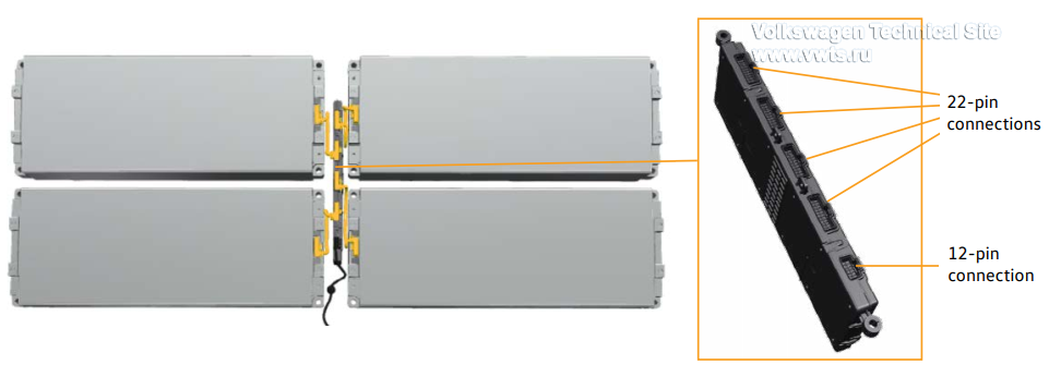
AX2 High-Voltage Battery 1 - J1208–J1210 Battery Module Control Modules

A maximum of four battery modules are connected to each battery module control unit.
Two or three control units are used, depending on the size of the battery.

Functions of the J840 Battery Regulation Control Module (through the J1208-J1210):
• Monitoring the cell voltages
• Monitoring the module temperatures
• Cell balancing

The 22-pin connections connect the battery modules control units to the individual battery modules.
The 12-pin connection is used for connecting other battery modules control units or the J840.
The VW ID.4 battery cells have passive balancing.
This means that all battery cells are discharged to the voltage level of the weakest battery cell using resistors.

 
1666633019468.png