High-voltage Safety Concept
Table of Contents
High-voltage System Overview
Wiring and Connector Concept
High-voltage System Components
Thermal Management
High-voltage Safety Concept
Driving Mode Selection
Safety Measures
The high-voltage safety concept was modified for the Volkswagen
ID.4.
Some of these are carryover from the previous high-voltage concept.
Safety measure overview:
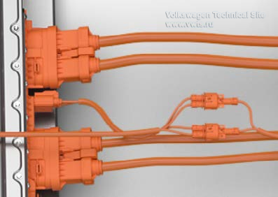
Color coding of the high-voltage wiring and connectors
Safety markings on all high-voltage components
Accidental contact protection
Emergency cut-out connections: Maintenance connector for high-voltage system
Fuse on the A-pillar with a small flag
Pilot line
Insulation resistance monitoring
Electrical isolation between high-voltage system and body (terminal 31)
Active discharging
Passive discharging
Crash shutdown
Monitoring of the high-voltage relays
Short-circuit test
Short-circuit shutdown
Detection of open circuits in high-voltage wires
Marking
Color coding of the wiring and connectors
All high-voltage connectors and wiring are orange to make identification easier.
Safety markings on all high-voltage components
All high-voltage components are marked with warning stickers.
There is an additional high-voltage warning on the lock carrier in the engine
compartment with a yellow background.
These warning stickers are relevant for the vehicle safety inspection.
Accidental Contact Protection
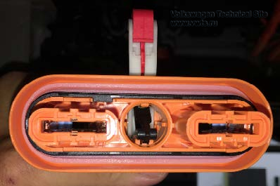
All high-voltage connectors are equipped with improved accidental contact
protection (IPXXB+, touch-proof). A smaller test finger is used.
High-voltage potentials inside of the components are sealed off by a cover with
coded screws and cannot be opened during service work.
Accidental contact protection has also been used inside the high-voltage
battery.
The Electromagnetic Compatibility (EMC) filters are adapted to the individual
requirements of the different high-voltage components.
They can be made of capacitors, restrictors or more complex circuitry.
Shielding of the high-voltage wires is not required.
The EMC measures are implemented in the high-voltage components by the EMC
filter.
Emergency Cut-out Connections
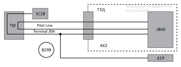
The emergency cut-out connections are the TW Maintenance Connector for
High-Voltage System in the left side of the engine compartment,
and the SC28 Fuse 28 (on Fuse Panel C) on the left A-pillar.
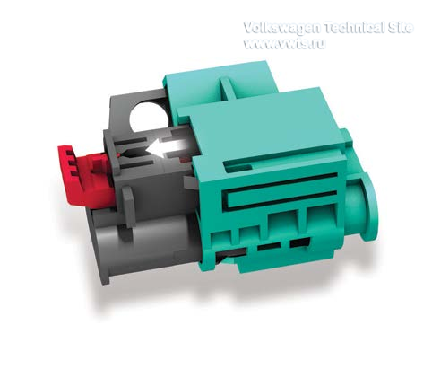
The TW Maintenance Connector for High-Voltage System
disconnects terminal 30 A and pilot line.
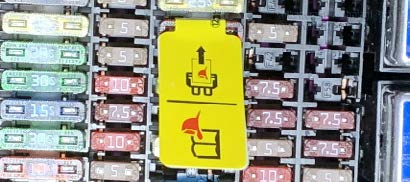
The fuse SC28 has a small flag on it. When removed, terminal 30 A is
disconnected.
The small flag is attached to allow quick removal without tools.
The small flag can be replaced separately and the fuse is commercially
available.
Terminal 30 A (previously terminal 30 C) in the VW ID.4 supplies both the
voltage for the high-voltage relay in AX2 High-Voltage Battery 1
and the supply voltage for the A19 Voltage Converter.
There is also a Bowden cable located in the trunk to release the charge plug if
there is a problem.
Pilot Line and Insulation Resistance Monitoring
Pilot Line
The pilot line is now only routed to the TW Maintenance Connector.
It was removed from other areas because all high-voltage connectors have
improved accidental contact protection.
It is monitored by the J840 Battery Regulation Control Module.
A19 Voltage Converter
AX2 High-Voltage Battery 1
B298 Positive Connection 2 (30) (in Main Wiring Harness)
J840 Battery Regulation Control Module
SC28 Fuse 28 (on Fuse Panel C)
TW High-Voltage System Maintenance Connector
T32j 32-pin Connector, Onboard Supply Connection, on AX2 High-Voltage Battery
1
Insulation Resistance Monitoring
The insulation monitoring checks the electrical isolation of the high-voltage
potentials to the chassis.
When the value falls below a threshold of 510 kOhm, a yellow warning lamp
illuminates on the instrument cluster.
A red lamp appears when the value falls below 90 kOhm. DC charging is either
deactivated or prevented.
The insulation resistance monitoring is initiated by the J623 Engine Control
Module and performed by the J840.
Among other things, it is part of highvoltage system activation, which is
monitored by the high-voltage coordinator.
Its function and circuitry is similar to the insulation resistance monitoring in
the e-Golf.
Active and Passive Discharging
Active Discharging
If there is an emergency shutdown of the high-voltage system, such as if a crash
or the TW Maintenance Connector is removed, the high-voltage system is
discharged within five seconds.
Active discharging is performed in the JX1 Electric Drive Power and Control
Electronics.
Passive Discharging
High-voltage components have capacitors in their circuitry.
Passive discharge guarantees that the voltage falls to < 60 V within two minutes
of disconnecting the components from the high-voltage battery.
Crash Shutdown
Following an accident that may damage components in the high-voltage system, the
high-voltage system is shut down and actively discharged.
Because a number of high-voltage components in the Volkswagen ID.4 are installed
very close to the outer body shell, severe and minor accidents are treated the
same.
This means that in case of an accident, the high-voltage potential is
immediately disconnected (by pyrotechnic means). This can be repaired in the
workshop.
The pyrotechnic disconnection is performed by the S415 Fuse for High-Voltage
Battery Interruption in the switching unit for SX7 High-Voltage Battery Control
Module, Negative Terminal.
Monitoring of the High-Voltage Relays and Short-Circuit Test
Monitoring of the High-Voltage Relays
Each high-voltage relay has a voltage tap before and after the relay
If an unintended condition is identified to be affecting one of the
high-voltage relays, the high-voltage system is deactivated until the defect is
eliminated
A lamp is illuminated in the instrument cluster
Short-circuit Test
When C25 Intermediate Circuit Capacitor 1 is being pre-charged, a current
measurement is performed
Short-circuit Shutdown
If a short circuit occurs during pre-charging, it is isolated and the
high-voltage system is not activated
If a short circuit is detected when the high-voltage system is already
activated, the high-voltage system is turned off
A lamp is illuminated in the instrument cluster
